Reduction Gearbox on Medium Speed Engines on Ships
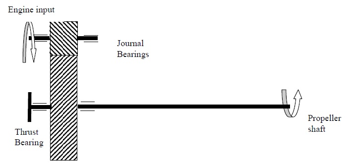
The sketch below shows a simple, single reduction gearbox suitable for speed reductions from 750 to 150 rev/min reduction (i.e. 5:1 reduction). The main wheel would contain two journal bearings for shaft support, as well as a thrust bearing to absorb the propeller thrust. The input shaft would only require simple journal bearing supports.
The gearings and bearings would be lubricated by a self contained lube oil system, with the gears being supplied by sprayers.
Maintenance on Reduction Gearbox
To minimise gear wear, the gear wheels are made from forged steel with post machining hardening. The gear tooth profile is produced using a horizontal machining process known as “Hobbing”. The profile of the tooth is formed on the hobbing tool, and this tool is rotated and passed over the forged gear wheel to form the tooth shape. As marine gearing generally have a helix angle for multiple gear tooth meshing in service, the gear wheel must be slowly rotated during the hobbing process. Once the gear profile is machined, then the gear wheel is hardened using induction hardening
process.
Gearing inspections should be carried out with minimal disturbance to the gear system or alignment. Hence the condition of the gear teeth will be used to establish that the gearing system is operating in a satisfactory condition. The following items would be inspected:
- Remove inspection covers to examine wear on gear teeth.
- Marks along length of tooth could be due to abrasive particles within the oil, so the oil sample report would be checked.
- Marks or pitting at the pitch line would indicate either overload or inferior properties of the lube oil, such as low viscosity. The previous operating records of the gearbox and the oil test results would be checked.
- Marks at one edge of the gear tooth could indicate gearing mis-alignment. The clearance at the journal bearings would be recorded, or dismantled if clearance measurements are difficult.
- The thrust bearing would be removed for inspection on the running face, and the pivot on the back of the bearing. Any defects could require a bearing replacement.
- The oil filters would be removed to look for particles, and to check the magnetic plug fitted at the filter core.
- The oil sprayers would be examined to security, and function testing using the auxiliary oil pump