Basic Principles of PID Controllers
Automatic controllers are used onboard ships for the adjustment of one or more parameters in a system. Function of the controller is to maintain the parameter as per desired value (value set by the operator). The parameter could be jacket water temperature (for engine jacket water cooling system), lubricating oil temperature (for engine lube oil system), fuel oil pressure (for boiler fuel oil system), etc. PID controls are commonly used for these applications. Advantage of automatic indicating controller is that it controls as well as indicates the parameter reading. Refer to the diagram and explanation below to understand the basic principle of PID controllers. These controllers are normally located near the variable measuring point so that use of a transmitter (to transmit parameter signals to the controller) is not required.
On-Off or Two Step Action
This is the simplest form of control. Here only two control positions are allowed; on or off. In the case of a valve, it opens or closes by the signal from the controller. Examples for such control system are; water level control for boiler cascade tank, air compressor cut in cut off control, temperature control for fuel oil storage tanks, etc. Let us consider the case of a fuel oil tank heating steam two step controller. It consists of a controller that continuously senses the system parameter (fuel oil temperature). This is called measured value. The desired value or set point (temperature of fuel oil to be maintained) is fixed by the operator. When the temperature of the fuel oil drops below set point, controller sent signal to the steam valve thereby passing steam through coils provided inside the fuel oil tank. Now temperature of fuel oil starts increasing. When the temperature rises to the set point, controller shuts the steam valve. The system response is illustrated down below.
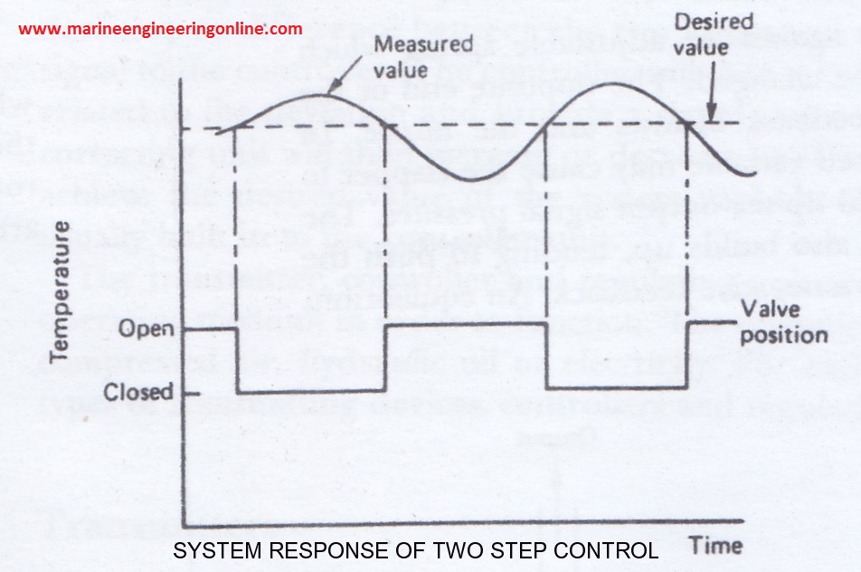
Now as we know there is a thermal inertia in this system. Or in other words the position of temperature sensor and that of steam coil is different. That is why we cannot observe an increase in temperature as soon as the steam valve opens. The same phenomenon explains why temperature is increasing even after the steam valve is shut. Anyway disadvantage of this control is the large deviation from the desired value or set point. Hence the application of such control is limited.
Proportional Action
This is a continuous control action in which the controller output is proportional to the deviation between measured value and desired value. Let us take an example of a simple water lever control as shown in the figure below.
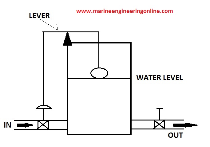
Consider a water tank with an outlet valve, a water supply valve, control lever on a pivot, control strings, and float as shown in the figure. One end of the control lever is connected to the float while other end to the water supply valve. The system is designed in such a way that, when float goes down supply valve is opened more thereby increasing water supply to the tank. Similarly an elevation of the float results in closure of the supply valve. At this point quantity of water supplied and flown out of the tank is same or the system is in equilibrium. Suddenly demand of water increases or the discharge valve is opened more. This result in reduction in water level inside the tank and causes float to lower. As float lowers it raises the control string connected to the water supply valve, thereby increasing the supply of water.
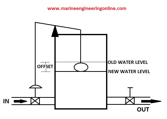
As shown in the figure above, a new equilibrium is attained by the system. Once again supply and demand of water is same. But we can see a drop in water level from the desired value. This deviation from the measured value and desired value is known as offset. It is an inherent property of the proportional control. Offset can be reduced but cannot be eliminated in such systems. The amount by which the input signal value must change to move the correcting unit between its extreme positions is known as proportional band. This concept can be made clear from the figures shown above. Move the position of the pivot towards right (closer towards the float). Now we can see that a small change in water level causes an amplified effect in opening or closing the supply valve. In other words the system becomes more sensitive. Also here the offset is reduced comparing to the scenario before. Similarly, moving the pivot towards the left cause minor changes for the supply valve even though float lowers or rises drastically. Here sensitivity of the system is less. It is clear that offset can be reduced to minimum when sensitivity is higher. But this results in hunting of the system. Hunting means excessive fluctuation of the measured value around desired value. System response to proportional action is shown below.

So far we have discussed proportional action with reference to a simple float and valve system. Same can be explained using a flapper-nozzle mechanism too. In fact such an example is much closer to the actual control system.
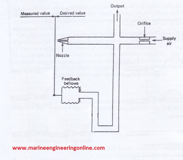
Referring to the diagram above, as the measured value deviates from set point, flapper moves closer to the nozzle. This results in an increase in output air pressure. This increase in output air pressure changes the controlled condition (parameter to be controlled), say by closing or opening a valve. At the same time the increased output air pressure act on the feedback bellows also. This negative feedback pushes the flapper away from the nozzle, thereby reducing output air pressure. Now the system is in equilibrium. Remember that an offset is inevitable here. Moving the nozzle away from the feedback bellows increase sensitivity and hunting of the system. Also moving nozzle towards feedback bellows reduces hunting and increases offset. So position of the nozzle (or Proportional Band) can be adjusted carefully to obtain a stable system with minimal offset and hunting.
Integral or Reset Action
Integral action or reset action is used in conjunction with proportional action, to remove offset from the system. Here controller output varies at a rate proportional to the deviation between measured and desired value. Refer to the figure below.
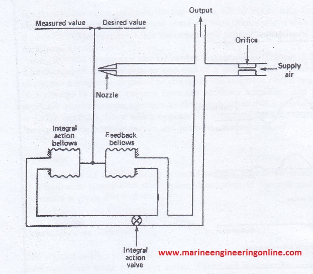
Here in addition to the feedback bellows, we have integral action bellows also. Consider the integral action valve is open. Now as the flapper moves closer to the nozzle because of a deviation, output air pressure increases, the same air pressure acts on feedback bellows to move the flapper away from nozzle to an equilibrium position. Now there is an offset. Again the same control air pressure acting on the integral bellows moves the flapper towards the nozzle to increase control air pressure. Hence a new equilibrium is attained with no offset. Note that all these actions take place simultaneously. When the integral action valve is fully open, integral action will be too fast that result in hunting. When the valve is crack open, there is no hunting but it takes long time to remove offset. In other words time required to remove the offset (Reset Time) can be adjusted by opening or closing integral action valve. Closure of the integral action valve means no integral action. Reset time to be set in such a way that system operates fast to remove offset and minimal hunting. All pressure control systems onboard ships are normally proportional-integral (PI) controls.
Derivative or Rate Action
Derivative action is utilized along with proportional and integral actions. This is applied in systems where time delay between changes in measured value and their correction is long. Example is temperature control for jacket water system. Here controller output is proportional to the rate of change of deviation. Refer to the figure below.
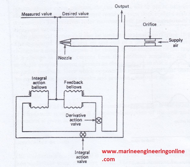
Here a derivative action valve is introduced as shown in the figure. Closing this valve any amount would introduce derivative action in the system. Consider the derivative action valve is closed 70%. When flapper moves towards nozzle because of a deviation, controller output pressure increases, the same pressure acts on the feedback bellows through the derivative action valve. As the valve is only little open, it takes time to move the flapper away from the nozzle by negative feedback, thereby allowing control air output pressure to be higher for long time, which again allow more time for corrective action. Also derivative action can be varied by adjusting opening or closing derivative action valve. When derivative action valve is fully open, there is no derivative action.
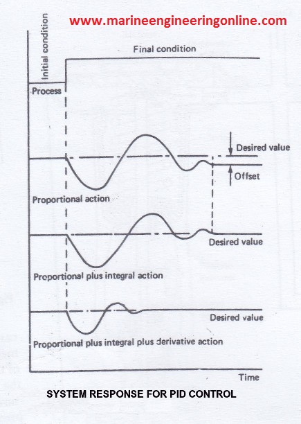
Response of a PID control action is also shown below.