Compressors – Working and Characteristics
Compressors are used to increase the pressure of a gas. Like pumps, compressors can be classified as either kinetic machines, which includes centrifugal and axial compressors, or positive-displacement machines, which include reciprocating and rotary compressors. The compressing medium or ‘gas’ depends on the application, such as, if air is used it is termed as an air compressor. Similarly if refrigerant is used, it is known as a refrigerant compressor. The type of compressor, its discharge pressure and discharge rate is dictated by its use.
Types of compressors
Here we discuss about two types of compressors that are commonly used in the industry.
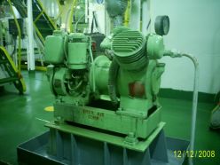
Reciprocating Compressor
Screw Compressor
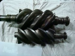
Screw compressors (also called as helical lobe compressors) are positive displacement machines in which gas is being compressed is forced through the casing by two screws. Unlike the reciprocating compressors which are also positive displacement machines, screw compressors does not typically require internal suction or discharge valves. In addition the flow from screw compressor is generally more uniform and has fewer pulsations than the flow from a reciprocating compressor.
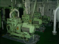
A twin screw compressor consist of two meshing helical rotors mounted on counter rotating parallel shafts that are enclosed within close-clearance casing. One screw is called driving screw which is coupled with a drive, say an electric motor, while the other screw is called as the driven screw, since it is driven by the driving screw. Gears used for driving the screws are called timing gears, since they are properly timed to maintain the close-clearance between the screws.
For screw compressors oil is injected into the screws while operation. There are mainly 3 functions for the oil, they are,
1) Sealing of the screws to prevent leakage of the gas
2) Lubrication of the parts, especially the screws, and
3) Cooling of the gas compressed, which results in increased efficiency of the system
Materials used for construction
Reciprocating Compressor
Piston Rings – Cast Iron
Screw Compressor
Casing – Cast or Ductile Iron
Where they are used?
Reciprocating Compressor
Reciprocating compressors are characterized with higher pressures and reduced mass flow rate. They are mainly used in high pressure applications since it can deliver air at about 30 – 40 bar.
3) Air conditioning systems also uses reciprocating compressors (Nowadays trend is changed to screw compressors).
Screw Compressors
Screw type compressors provide air at increased mass flow rate but with reduced discharge pressure around 8 bar. Hence applications are also in low pressure systems, such as,
Cycle of operation
Consider one cycle of operation in a reciprocating compressor.
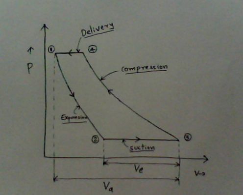
The process that occurs in a cycle 1-2-3-4-1 are explained below
The process that occurs in a cycle 1-2-3-4-1 are explained below
- (3) – (4) – As piston travels from BDC to TDC air trapped inside the cylinder is compressed.
- (4) – (1) – As piston approaches TDC discharge valve opens and compressed air is delivered.
- (1) – (2) – Undelivered air trapped in the clearance space is expanded as piston moves down.
- (2) – (3) – When trapped air in the clearance space is expanded to atmospheric pressure, further downward movement of the piston creates a vacuum inside the cylinder and thereby atmospheric air enters through suction valve.
Again cycle repeats.
Voleff = [ ( Ve / Va ) * 100 ] %
Then why clearance space?
How to measure clearance volume
Why cooling is required?
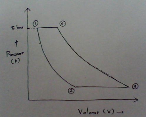
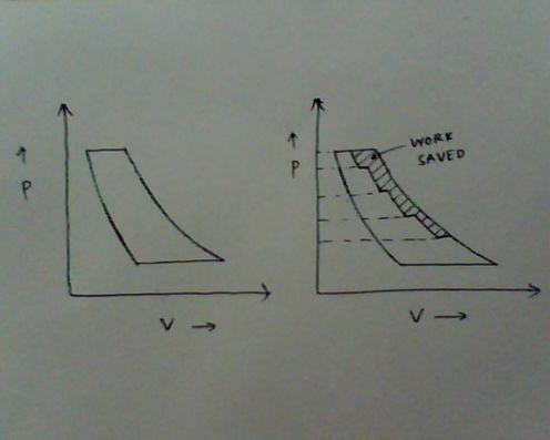
Above cycle compresses gas from atmospheric pressure to 8 bar in a single stage. The area enclosed by the points 12341 represents the work of compression in a single stage compressor. Also see the cycle or Pressure-Volume diagram (P-V) below which compresses gas from atmospheric pressure to 8 bar in two stages.
Two stage compression is shown below.
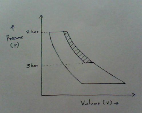
Here first stage compresses gas from atmospheric pressure to 3 bar and then gas is cooled isobarically (at constant pressure, refer diagram above). Now gas is again compressed to 8 bar. Now we can see that the work of compression corresponding to the shaded area in the diagram is saved by incorporating an inter cooling between two stages. Hence when comparing with a single stage compressor work can be reduced by inter cooling in a multistage compressor.
Work can be reduced further by increasing number of stages and inter cooling, but as the number of stages increases design becomes complex, constructional cost increases, maintenance cost also increase, which may nullify the effect of work saved during operation. This is the limiting factor for more number of stages.
Refer figure below.

The indicator card (PV diagram) above shows 3 types (or processes) of compression possible.
Isothermal Compression
During the process of compression, whatever heat produced is taken away by a cooling medium. In other words, it is the compression , keeping temperature of the gas constant. For a process to be isothermal, the process must be very slow, which is impractical. From the indicator card, it is clear that, work of compression is minimum in isothermal compression.
Also,

Adiabatic Compression
Whatever heat produced during compression is kept inside the gas only, or heat transfer is zero in an adiabatic compression. For a perfect adiabatic process, process must be very fast. All the thermodynamic process resembles adiabatic process. It can be seen from the indicator card that, work of compression is maximum in adiabatic compression.
Also,

Specific heat is defined as the heat energy required to raise the temperature of unit mass of substance by unit degree.
Polytropic Compression
Polytropic compression is neither isothermal nor adiabatic. It comes in between.
Also,

Work of compression can be minimized by isothermal compression. But compression is practically a fast process. So it better resembles an adiabatic process. Jacket cooling of compressor makes the compression polytropic.
Now the only way to make the compression more isothermal is, by dividing the process to a number of stages. Between every stage inter cooling of gas is done. Hence the work can be saved substantially.
Refer the diagrams below.